
1930s Singer 201 Tension Assembly
 02-23-2021, 11:20 PM
#1
Member
Thread Starter
Join Date: Feb 2021
Posts: 8
Dear all,
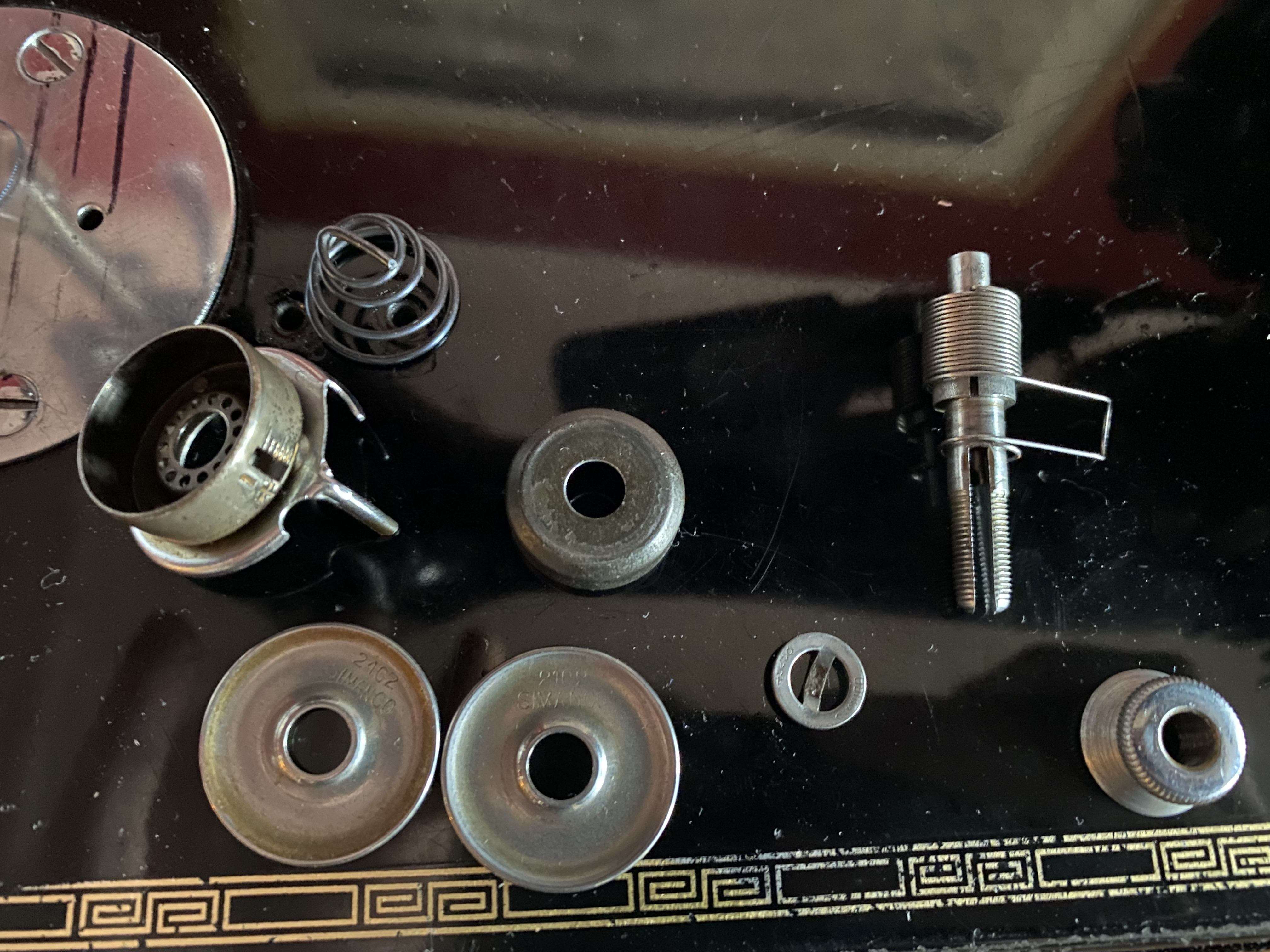
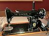
first of all let me thank you for all the information I already found here. I recently got an old Singer 201 from a friend in the family and have been trying to get it to run smoothly. It is a 1930s version build in Wittenberge, Germany. One of the last pieces in the puzzle is the tension assembly as the thread spring was bent I had to get a new one. Unfortunately this is a singer without the dial later Singers used. It only uses a little bent thingy to show the tension which is totally fine. But I cannot for the life of me figure out how to assemble it correctly. Does anyone have any idea or a manual that shows this particular version of tension assembly? I couldn't find one anywhere.
Any help is appreciated,
Best, Robert
 02-24-2021, 05:25 AM
#2
Senior Member
Join Date: Jan 2015
Location: Wisconsin
Posts: 474
Robert, it looks as if this assembly is very similar to that on the 115. The little knob on the knurled thumb nut is not the indicator, rather, the window on the short cylinder gives you a place to view the compression of the beehive spring. That knob is a device to adjust the fit of the thumb nut to the mechanism, allowing one to adjust to get a full range of tension, if numbered, from 0-9.
I'll have to resize a photo to post here, I do have a photo with the 115 sequence. I hope someone beats me to it!
ETA: nope, the recent photo I found is from a a 1936/37 15-91 with nickel plate stitch length plate. I'll have to look further for the 115 project.
I learned the hard way, too, to carefully disassemble, layout the sequence, and take a photo. But then, that assumes the person who messed with it before me installed it correctly.
Last edited by WIChix; 02-24-2021 at 05:35 AM.
02-24-2021, 05:51 AM
#3
Senior Member
Join Date: Apr 2020
Location: South of St Louis
Posts: 836
Welcome to the board! I would start with page 26, of the manual itself, from here
https://cdn.shopify.com/s/files/1/07...99796216700119
It looks as though your numbered dial, part Y from the manual, is inside of the housing, part Z from the manual.
It may not be an exact match for those parts you have, but it's a start.
https://cdn.shopify.com/s/files/1/07...99796216700119
It looks as though your numbered dial, part Y from the manual, is inside of the housing, part Z from the manual.
It may not be an exact match for those parts you have, but it's a start.
02-24-2021, 06:31 AM
#5
Member
Thread Starter
Join Date: Feb 2021
Posts: 8
Thank you all for the help. Weirdly enough my washer doesn�t have a finger and it doesn�t look like it ever had one. So there is no breakage or similar. Which is in part why the assembly doesn�t fall in line with the 201s dial assembly. Also the �dial� is connected to the plate that some of you have separately. Which is why I am not sure where to put the round end of the spring.
02-24-2021, 09:33 AM
#6
Senior Member
Join Date: Apr 2020
Location: South of St Louis
Posts: 836
OK here goes...
I am looking at another manual, for a 201k, for reference, pages 24/25 of the manual itself, not the PDF file:
https://cdn.shopify.com/s/files/1/07...ER-201K.pdf?15
There are at least 2 issues to deal with on this, 1. how to lift the tension when you lift the presser foot lever, 2. The "eyelet" of the take up spring (see pg 25 part marked N).
My suggested order of assembly assumes you are removing that eyelet on the spring, or getting another spring without one, such as this:
https://www.vintagesingerparts.com/c...-numbered-dial
I have marked up your original picture with numbers for the parts in more or less the order I would use, no number on the spring itself, just the post.
1. Discs 2 and 3 go on 1 from the slotted end, with the flared edges of the discs facing out, opposite each other but inside the squared off loop on your spring
2. Part 1 with the discs on it goes into 4 with the arm of the spring from where the eyelet was removed floating in one of the spaces/gaps on part 4 between the housing and the base plate with the long finger, or that arm being cut short enough that it won't hit the housing
3. Part 5, turned over from how it is in your picture, slid onto part 1, the post, with the crossmember of part 5 in the slot
4. Part 6, turned over from how it is in your picture, onto part 1, the post, on top of part 5; I am assuming part 6 has edges on it that will allow the part 7, the spring, to fit into it, if not turn it over
5. Part 7, the spring, with the crossmember in the slot of part 1, the post, on top of part 6
6. Part 8, the thumb nut, screwed onto the post directly contacting part 7, the spring
I hope this helps. I can't see any other way with the parts in your picture.
02-24-2021, 11:42 AM
#7
Senior Member
Join Date: Apr 2020
Location: South of St Louis
Posts: 836
Even though I said I can't see any other way, I see at least one other way:
1. Discs 2 and 3 go on 1 from the slotted end, with the flared edges of the discs facing out, opposite each other but inside the squared off loop on your spring
2. Part 5, turned over from how it is in your picture, slid onto part 1, the post, with the crossmember of part 5 in the slot
3. Part 1 with the discs on it goes into 4 with the arm of the spring from where the eyelet was removed floating in one of the spaces/gaps on part 4 between the housing and the base plate with the long finger, or that arm being cut short enough that it won't hit the housing
4. Part 7, the spring, with the crossmember in the slot of part 1, the post, on top of part 4
5. Part 6 onto part 1, the post, on top of part 7, the spring; I am assuming part 6 has edges on it that will allow the part 7, the spring, to fit into it, if not turn it over
6. Part 8, the thumb nut, screwed onto the post directly contacting part 6
02-24-2021, 12:01 PM
#8
Member
Thread Starter
Join Date: Feb 2021
Posts: 8
Dear JoeJr,
thank you and all of you so much for taking so much effort!
Your detailed descriptions are fantastic. Thinking about �how to lift the pressure when the foot is up� had me thinking as well as part number 5 is not attached to number 4 as it is with �newer� Singers. So I think you are right with your second idea that number 5 has to come before number 4 so it can press against number 4 when the pressure lifting pin is moving forward so tension is disengaged. I didn�t know there were springs without the eyelet so snipping that off sure helped a lot getting it into the housing. That couldn�t really be done with the eyelet on.

As you can see the complete assembly looks nearly like a singer with a black numbered dial. Now I think I need to adjust the bobbin tension, as that seems to be not high enough to resist the upper thread on any upper tension.
I attached a video to show you how it is working. Would you agree that that looks about right?
trim.EE9EE3BF-0881-432F-B552-851E8E994D5D.MOV
And one final question as you all got me thinking: is this really a 201 or another model?
thank you and all of you so much for taking so much effort!
Your detailed descriptions are fantastic. Thinking about �how to lift the pressure when the foot is up� had me thinking as well as part number 5 is not attached to number 4 as it is with �newer� Singers. So I think you are right with your second idea that number 5 has to come before number 4 so it can press against number 4 when the pressure lifting pin is moving forward so tension is disengaged. I didn�t know there were springs without the eyelet so snipping that off sure helped a lot getting it into the housing. That couldn�t really be done with the eyelet on.
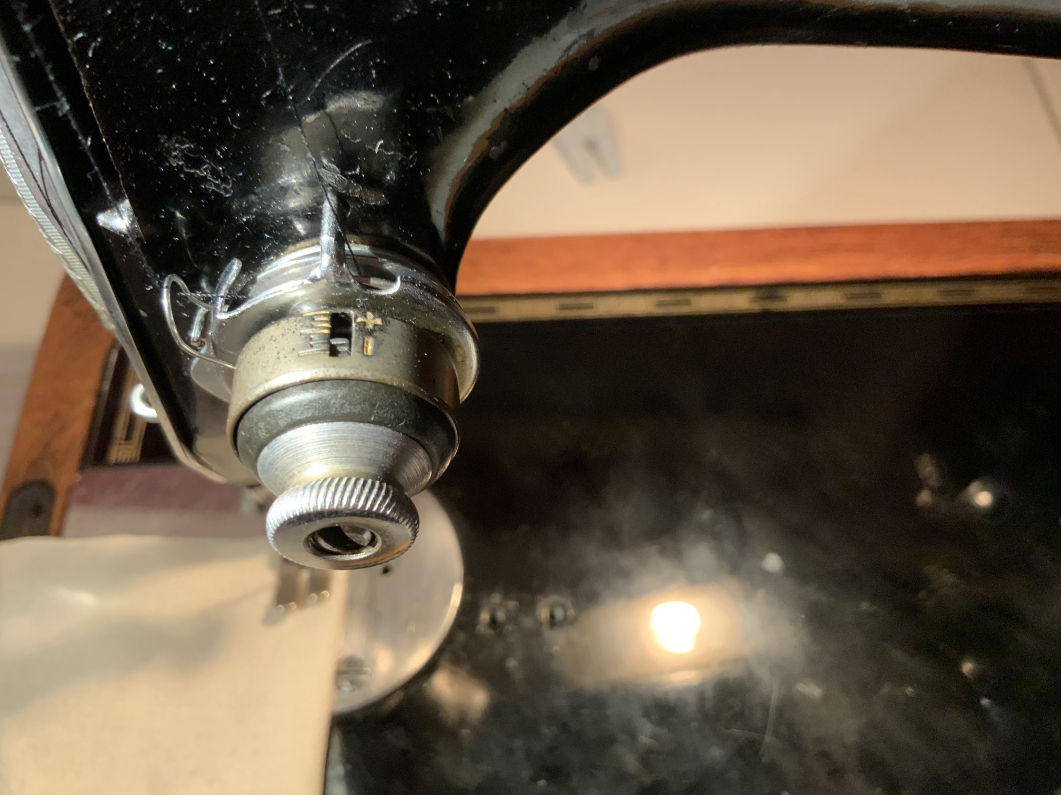
As you can see the complete assembly looks nearly like a singer with a black numbered dial. Now I think I need to adjust the bobbin tension, as that seems to be not high enough to resist the upper thread on any upper tension.
I attached a video to show you how it is working. Would you agree that that looks about right?
trim.EE9EE3BF-0881-432F-B552-851E8E994D5D.MOV
And one final question as you all got me thinking: is this really a 201 or another model?
 02-24-2021, 12:12 PM
#9
Senior Member
Join Date: Apr 2020
Location: South of St Louis
Posts: 836
See if you can find the serial number here:
http://ismacs.net/singer_sewing_mach...-database.html
I have not seen a machine with that configuration, but someone here will likely know.
If it's from Germany, maybe this information will help:
https://www.singersewinginfo.co.uk/201
http://ismacs.net/singer_sewing_mach...-database.html
I have not seen a machine with that configuration, but someone here will likely know.
If it's from Germany, maybe this information will help:
https://www.singersewinginfo.co.uk/201
